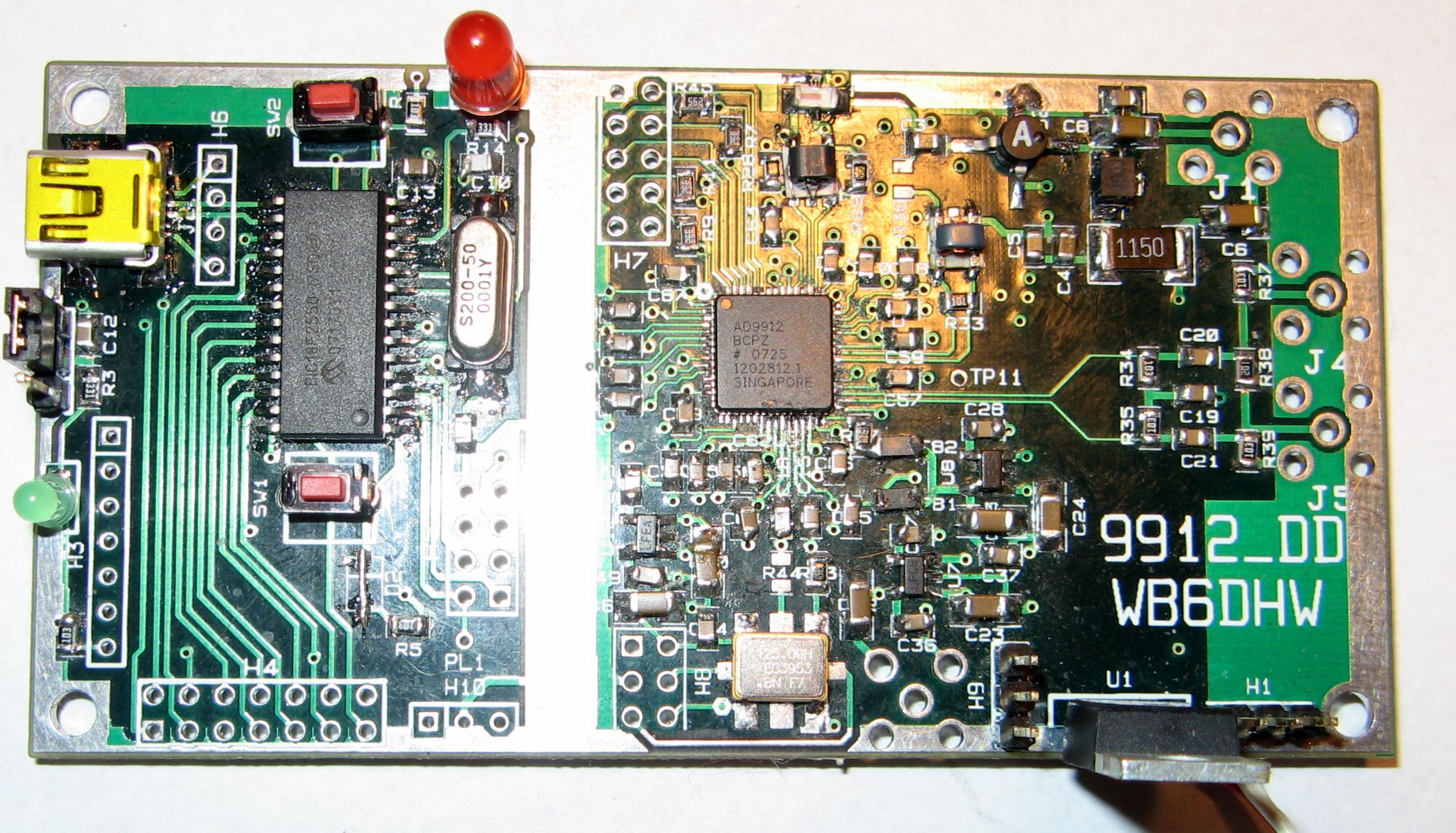
DDS Clock The board contains provision for either an on-board 125 MHz "canned" oscillator or an external oscillator. An SMA connector is provided forexternal oscillator input.Controller A PIC18F2550 is the controller. This will allow control from the USB bus. Stand alone operation with an external LCD, rotary encoder andswitches is possible with additional controller firmware. All I/O pins are brought out to headers. The controller is isolated from the DDS sectionwith a separate power pour and a ground strip between the 2 sections to allow for shielding if necessary. Power Supply Four 1.8V regulators, and 2 3.3V regulators are provided for the various DDS chip supply pins to isolate the various sections. An additional 3.3V regulator is provided for the closk oscillator. Output Circuitry The I and /I DDS outputs will be combined in a transformer, passed through a low pass filter to filter the undesired alias responses, and amplified by a mmic amplifier. Output is via an SMA connector. The comparator inputs and outputs are not used, however are available via headers. Status 1-19-09 Production boards are in stock..
|